TECHNICAL |
PTF 17-22
|
|
|
[ Technical ] CHAPTER IHULL AND MECHANICALSECTION IHULL CONSTRUCTIONREFERENCES
GENERAL REMARKSTo attain the highest possible strength with comparatively low weight of hull, the structure, with longitudinal girders, bulkheads, web frames and frames are designed according to the most modern methods of construction, utilizing light materials, laminating processes, plywood construction and double planking. All wood materials are first grade, free from sapwood and suitable for the purpose. All plywood is waterproof marine type. MIL-P-18066. All laminations, scarves, etc., are glued in accordance with the requirements of MIL-A-22397. All aluminum parts are of seawater-resistant alloy, treated with primer F-117 and F-84 before other paint is applied. All fastenings are of non-corrosive stainless steel in all principal construction members. GENERAL HULL CONSTRUCTION
|
| The longitudinal strength is obtained with girders (10), (named A, B, C,), deck stringers (II) and side stringers (12). Web frames (15) at frame 53, 55, and 60, and brackets (16) at frame 58 and 60 are made of seawater-resistant aluminum. The stem is protected with a .125 in. stainless steel shearwater, shaped to fit the stem from stem head to frame 16. The corners of the transom ·are protected by .125 in. thick stainless steel strips. The hull is fitted with necessary doubling for stern tubes (17), underwater exhaust (18), propeller brackets (19), and rudder stock (20). In the bottom of the after peak there are two bottom frames (21), at frame 67 1/2 and 68 1/2, as a reinforcement for the brackets. |  |
| The two gun foundations are built as integral members of the hull structure and distribute stresses to the bulkhead, web frames and main longitudinal girders. The foundations (22) are made of mahogany with reinforcement of seawater-resistant aluminum. The foundation (23) is made of mild steel with stanchions of seawater-resistant aluminum. Bottom frames (21) are mounted at frame 48 1/2, 49 1/2, 52 1/2 and 53 1/2 to obtain the stress from the gun foundation. The main engine beds are of light alloy castings mounted on "A" and "B" girders, which are strengthened by aluminum plating on each side between bulkheads at frame 49 and 64. Vee-drive gears are mounted on light alloy foundations fastened to girders "A" and "B" | 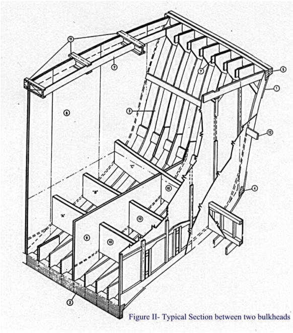 |
The engine installation hatch (24) on the aft deck is constructed of aluminum. The hatch coaming is bedded watertight to the deck. The bridge is built of waterproof plywood. The front side (25) is especially reinforced with laminated fir stiffening ribs covered with plywood .
Anchor: A 90 pound Danforth anchor is placed on the foredeck and lashed to the deck. Stowed in the forepeak is 30 ft. of 1/2 in. chain attached to 300 ft. of one-inch nylon line. This is easily accessible through a deck plate just to starboard of the anchor. The bitter end of the anchor line is securely fastened to the hull.
Mooring Fittings: There are five bollards and four cleats located about the boat to facilitate mooring. There is also provided an aluminum bow chock. The boat is equipped with four mooring lines of one inch nylon 100 ft. long.
Life Rafts: The boat is equipped with two self-inflating life rafts manufactured by Elliot. The raft will automatically release from its cradle and inflate should the boat sink. Servicing information on the rafts is found in the Elliot Manual supplied with the boat.
Dinghy: A nine-foot fiberglass dinghy is supplied with the boat and is lashed to the engine hatch just forward of the engine room air inlet. The dinghy is equipped with oars, removable row locks and 10 ft. bow and stern painters.
Life Lines and Stanchions: The stanchions are of aluminum tubing except for two stanchions on each side in way of the main engine hatch that are stainless steel and are removable. The life line is plastic-coated stainless steel cable of 1/4 in. diameter. The lifelines may be tightened by turnbuckles located at the center fore and oft stanchions. The gangway lines may be tightened at the pelican hooks.
Life Rings: Two life rings are supplied with the boat and are located on either side of the deckhouse. They are equipped with 180 ft. of 3/8 in. line and an electric self lighting water light.
Shore Line: The connection box for the shore electrical line is in the starboard side of the deckhouse towards the oft end. The boat is equipped with 159 ft. of shore cable and is stored in the starboard aft compartment of the deckhouse.
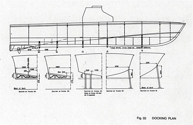
The position of the various keel blocks, chocks, and supports is shown on Docking Plan - PTF-17-145-4315018.
In certain circumstances, variation from these positions can be accepted, but it is important to have a good support under frames 53 and 60 to take the weight of the engines.
The following should be observed during docking:
|
a) Before docking, all easily removable weights such as ammunition, mines, etc., should be removed. This is also necessary for safety. b) There should not be more than 30% of fuel in the storage tanks; supports similar to that shown for frame 43 should be applied at frames 40 and 46 according to amount and location of fuel. |
 |
NOTICE: Only in emergency should docking be performed with full fuel tanks. Supports must be replaced as quickly as possible after docking.
c) Keel blocks shall be placed in a straight line, 1200 mm (approximately 47 in.) apart, and chocks shall be placed under frames 53 or 60.
d) When the boat has been docked, supports have to be placed under the chine at frames 16 and 32, and under the transom at the center line and port and starboard sides. Care should be taken that the chocks at frame 60 do not touch the water inlet scoops or the underwater exhaust outlets.
The watertight bulkheads are marked on the hull with small triangular metal plates below the rubbing stroke. The center lines of the rudders are marked on the transom with small triangular metal plates below the waterline. The boat center line is marked on the deck with one triangular metal plate at the transom and one abaft the forward hatch.
There must be a minimum distance of 1000 mm (approximately 40 inches) from the bottom of the keel to the floor of the dock to give clearance for the propellers.
The following distances must be kept between the bottom of the keel and the floor of the dock in order to carry our certain repairs:
Removing the rudders - 1550 mm (approx. 61 inches)
Changing propellers - 1000 mm (approx. 40 inches)
Changing propeller brackets - 1700 mm (approx. 67 inches)
Withdrawing propeller shafts - 1700 mm (approx. 67 inches)
To withdraw the propeller shaft, a distance of 4800 mm (approx. 16 feet) has to be kept clear of obstructions abaft the stern.
The watertight hatches are constructed of aluminum, aluminum bronze and stainless steel in accordance with the reference plan. Adjustments can be made to the dogging mechanism to control the tightness of the hatch. The pins over which the dogs lock are camground and may be rotated to allow tighter or looser dogging action.
The watertight doors are constructed of plywood with stainless steel and bronze dogging mechanism. Dogging is accomplished by rotating a cam plate in the center of the door. This in turn extends the dogging arms into sockets in the door frame. Adjustment of the dogging pressure is made at the bracket at the end of each dog. Adjusting the bracket toward the door increases the dogging pressure, while adjusting the bracket away from the door decreases the dogging pressure.
It is quite important to keep the cam mechanism well lubricated. Lack of lubrication can cause excessive wear and add resistance to the dogging operation. A lightweight grease like Lubriplate or equal should be used.
All necessary information concerning the main engines and their servicing requirements can be found in Napier Publication 505 entitled Maintenance Manual for Deltic Marine Engine. (NavShips-341 -3530).
In on emergency underway on one engine, it may be necessary to start the other engine using the force of the trailing propeller. This is accomplished in the following manner:
Make the stopped engine ready for start, and set the control lever in "Ahead" position.
Increase speed on the operating engine to 1100 RPM
Open the valve on the "Trailing-in" oil pipe, first on the running engine and then slowly open the valve on the engine to be started.
Close both valves as soon as the engine has started.
Due to the transfer of oil from one engine to the other, oil level in the service tanks should be checked.
Description: The main engines are fitted with a mechanical type remote control to the control room. The type used is Teleflex Marine Controls, made by Teleflex Products Ltd., Essex, England.
Main Engine: Gear changing and speed control: The control system is designed to permit operation of the engines from either the control room or the bridge. The function of gear changing and speed selection is carried out by a lever from either the control room or the bridge.
The levers are connected in tandem through a single cable and junction box to both the hydraulic governor and the hydraulic control unit. This arrangement permits the automatic selection of the correct engine speed during gear changing and the retention of the required gear during subsequent speed change. For further information, see Deltic Maintenance Manual, Publication 501, Article 7.1. Each engine is stopped by a hand-operated shutdown lever situated in the control room beside the speed control lever. When the lever is moved to "Stop", the shutdown cable moves the governor shutdown lever and shutdown probe lever, which in turn depresses the servo valve to stop the engine.
All necessary information concerning the Vee-drives and their servicing con be found in Napier Publication #244.
All necessary servicing functions to the two auxiliary engines are outlined in Onan Service Manual for MDJC series engines. (NAVSHIPS No. 0961-026-5010).
Each propeller shaft (14) is supported in a stern tube (8) and (9) and propeller shaft bracket (15) at an angle of 12" to the base line. It is directly coupled to the output coupling flange of the vee-drive. The vee-drive with an included angle of 1880 is mounted to allow the engine to assume an angle of 60 to the base line. From the input coupling flange of the vee-drive a cardon shaft is secured to the engine output coupling flange.
| Each stern tube is constructed in two sections of aluminum-bronze castings, one inboard (8) and the other outboard (9) on either side of the hull as shown in the figure. Each section with its integral base plate is secured by through bolts to a stiffened section of the hull in the vicinity of the stern tube. Port and starboard construction are contoured to conform with the bottom of the hull. The outer section contains a Cutless Bearing (10) of 4 1/4 in. dia., Type "Nicety ", made by Goodrich Cutless Bearings. Water lubrication of this bearing is partly supplied from holes drilled at the forward end of the casting. |  |
To the forward end of the inner section a self-aligning stuffing box (4) and a stern gland (3) is secured by means of a special rubber Sleeve (6) and hose clamps (7). For cooling and lubrication purposes, salt water is supplied from the main engine salt water re-circulating system to the casting as shown in the figure. The Propeller Shaft Brackets (15) are contoured for port and starboard sides to conform with the bottom of the hull, but in all other respects they are identical. The brackets of cast aluminum-bronze are of "P" form design. Each bracket is secured to 3 stiffened port of the hull by through bolts.
A Cutless Bearing (17) of identical dimensions and type as fitted to the stern tube is also fitted in the strut bracket. Lubrication for this is supplied by water taken in at the forward end of the strut. Each propeller shaft (14) of aluminum-bronze is designed so that the ends are identical and in certain circumstances the shaft could be reversed . The shaft coupling flange (2) is secured by a key (26) and a nut (i), and the nut is locked by a special plate arrangement. The propellers (22) of aluminum-bronze castings are similarly secured by key (26) and nut (24), but the' locking for the nut is by three retaining screws (23) topped through the side of the propeller and into a groove in the nut.
The propellers have the following dimensions: Diameter 47 in., Pitch 62.4 in., Weight 120 kg (265 Ibs.), and are designed in England by Mr. Selman in cooperation with Boat Services Ltd. A/S. (Manufactured by Federal Propeller). When viewed from the after end, the port propeller turns in a counter-clockwise direction, while the starboard turns in the clockwise direction. For protection against electrolytic corrosion, zinc anode (25) is mounted at the aft end of the strut palm.
(Oil or grease must not be used on the Cutless Bearings)
During the construction of the hull, certain fixed datum points are obtained and are carefully marked to facilitate future maintenance.
These datum points are marked with triangular shaped metal plates and from these points the necessary measurements can be taken. When checking the propeller shaft, stern tube and propeller bracket alignment, a wire is held taut between the triangular plate mounted on the bulkhead frame 49 and a point subtended below the datum point on the outboard side of the transom as stated below.
The initial datum point of the alignment of the propulsion machinery is the forward edge of frame 55. (See Figure). By means of a wood block fixed to bulkhead frame 49, the distance of 2100 mm (6 ft. 10 43/64 in.) from the frame is obtained.
The forward point for the alignment is found 1087 mm (3 ft. 6 25/32 in.) above base line and 1200 mm (3ft., 11 15/64 in.) from the center line of the boat. The point is marked with a bronze triangle on the wood block.
The after point for the alignment wire is positioned 613.3 mm (2 ft. 1/8 in.) below base line and 1200 mm (3 ft. 11-15/64 in.) from center line of the boat. A bronze plate with groove for a plumb line is attached to the transom. The point for the alignment wire is found 1200 mm (3 ft. 11-15/64 in.) down on the plumb line from the lower angle of the triangle. The accurate distance from frame 55 which should be 5900 mm (19 ft. 4-9/32 in.) is compensated for when the bronze triangle is mounted.
When the boat is built, the alignment tolerances in bracket and stern tube are set to 0.016 in.. This alignment is done while the boat is still laying on the building slip. These tolerances are probably of no value when the boat is later put into a slipway. In this respect, we consider that alignment tolerances for brackets and stern tubes, if they are checked for any reason, ought to be a matter of experience with this kind of boat.
If, for some reason the vee-drive should have to be removed, provision should be made to take the load of the inboard end of the shaft when the coupling is on. This is best done by means of a bearing attached to web frame 53. The bearing should be lined up with the stern tube and bracket.
The vee-drive is mounted on the foundations, and is lined up when the center of the upper (input) flange is 853 mm (2 ft. 9-35/64 in.) from the wood block (triangle point) on bulkhead frame 49 and the same center 237.4 mm (9 ft. 21/64 in.) above top of "B " girder. These points are found 1200 mm outboard from the center line of the boat. When the shaft coupling is connected, the distance from end of the shaft coupling flange to the wood block should be 880 mm (2 ft. 10-5/8 in.).
The vee-drive is lined up in the ordinary way by using a feeler gauge with the female coupling on the shaft entered on the male coupling on vee-drive coupling (output). The feeler should preferably not be bigger than 0.020 in., to avoid any mistake in the distance between check point and coupling. Slots in the female coupling allow the feeler to be entered in four places, and checking should be done at top, bottom and both sides. The propeller shaft flange and vee-drive flange should be turned through 360deg, checking with the feeler every 90deg.
| The alignment tolerance is 0.002 in. When the
alignment of propeller shaft flange to vee-drive flange is
completed, it is necessary to check the alignment between engine and
vee-drive before the shims are fitted under the engine feet.
|
In a new installation an alignment jig is used for building up, filing and drilling the foundations and shims, and a main shim should, there fore, as a rule never be changed when such a jig is not available. The main engine has flexible mounting brackets and could, therefore, not be used for fitting the main shims. However, changing the main shims should not be necessary in a finished installation, and shims will do the job for any misalignment that can occur. The distance between vee-drive flange and engine output flange is 20 in.
For checking the alignment of the engine to vee-drive, a dummy shaft should be used as the cardon shaft is flexible. This dummy shaft should have a flange for bolting to the engine output flange at one end, and a bracket for supporting a dial micrometer to read parallel alignment as well as alignment on the circumference.
Alignment tolerances here are: Parallel - .005 and circumference .OG7.
The steering arrangement consists of three main components: (1) Rudders with rudderstocks, bushing and stuffing boxes. (2) Steering Equipment. (3) Emergency steering.
The boat is fitted with two cantilever spade rudders, manufactured by the boat yard. The rudder and stock are made in one piece of aluminum- bronze. (Weight 140 kg. - 310 Ibs.) The rudder-stock tubes with flanges and stuffing boxes are made of aluminum-bronze, and the bearings are made of Micarta. The flanges are fastened to the hull with through bolts of stainless steel.
The rudders are set parallel in relation to the boat center line; this has been found by experiment to be the best compromise between boat speed and maneuverability. If a rudder is changed, it may be necessary to check the rudder angle. The steering equipment is hand hydraulic and consists of two hydraulic cylinders actuated by a rotary hydraulic pump. There is also in the system a reservoir, a relief valve and a by-pass valve. The system is manufactured by Hynautic Marine Division of Fluid Controls, Inc., and all necessary service information can be found in the "Hynautic Installation Instructions", supplied with the boat.
There is also supplied a system for emergency steering of the boat. An emergency steering tiller, stored in the lazarette can be inserted through a deck plate on the starboard side near the transom. This tiller fits over a shaft connected directly to the starboard rudder. The by-pass valve, clearly marked in the lazarette, must be opened and then the boat may be steered with the emergency tiller.
The air compressors are mounted in the lazarette and are used to obtain 450 psi air to start the main engines. The compressors are manufactured by Ingersol-Rand and all servicing information can be found in the Ingersol-Rand Manual supplied with the boat.
The CO-2 system consists of three storage bottles, pipelines with spray nozzles and manual release equipment on deck. The CO-2 storage bottles are placed on foundations in the forward part of the engine room on the starboard side. The capacity of each bottle is 50 Lbs.. Total capacity is 150 Lbs. CO-2 gas. The pipelines consists of 3/4" and 1/2" copper pipes fitted below deck throughout the engine and control room. Spray nozzles are fitted in both compartments. The three storage bottles installed in the boat can deliver CO-2 gas to the tank and control room and to the engine room. room.
Each 02 bottle is fitted with a quick-release valve. These valves are remotely controlled by the wire mounted in 1/4" copper pipes. The remote control boxes are placed on the oft part of the bridge. If the handle marked "Engine Room " is pulled, this will open the valve that directs CO-2 to the engine room spray nozzles. The handle marked "C02 Release" must then be pulled to release CO-2 into the system. As the valve to the tank room will then remain closed, the CO-2 gas will be led to the engine room only. If the handle marked "Tankroom " is pulled in conjunction with the valve marked "CO-2 Release", then the CO-2 gas will be led to the tank compartment only.
Hand fire extinguishers are placed in all sections except the crew's head and the lazarette.
There are two types of extinguishers on board, 10 lb. and 20 lb powder extinguishers and 5 lb. CO-2 extinguishers. Instructions for the use of these extinguishers are printed on them and are normal for the two types.
NOTE: In case of fire, all hatches, ventilators and doors should be closed. The exhaust fans and air conditioner will stop automatically when the CO-2 system is discharged.
| For towing purposes each boat can be fitted out with a bridle made up of mooring lines and anchor lines. The use is shown on the figure . The bridles are fastened to the bollards and one or two anchor ropes are used as tow-rope, the distance between the boats will then be approximately 350 or 650 feet. A towing speed of approximately 12 knots should not be exceeded. |
NOTE: The bollard and bow chock in center on the fore
deck should not be used for towing.
The two outboard bollards on fore and aft deck are strengthened below
deck.
![]()